If you’re planning to purchase any used woodworking equipment or machinery from any of the many sources available on the used machinery market, there are several important points to carefully examine on the machine before you make the purchase.
Keep in mind:
- You can call us before you buy the machine. This could save you some significant expense.
- We only sell remanufactured machines that have current and “like new” standards, so we won’t try to sell you one of our used machines that hasn’t been completely remanufactured and brought up to the levels of safety that are required today.
- Complete information is available about every machine and any other machine we’ve built back as far as 1930. The original bill of material, an operator’s manual and other service related information is available for all of those machines through our service department.
- While there is no way for us to determine the specific condition of a saw over the phone, factory technicians are available to examine your equipment and make an accurate assessment of the cost to return any machine to proper working order.
If there is any way we can assist you in evaluating your existing rip saw, or a rip saw you are considering for purchase, please contact us.
As you begin your examination of a potential used machine, we suggest you look at the following issues in this order of importance:
Safety
Remember that like all self-feeding rip saws, the Machine has potential for kickback of material. Since 1930, this potential hazard has been controlled by a cam-operated, upper anti-kickback finger curtain, and since 1995, a second lower finger barrier in the work table. Be absolutely certain that these systems are intact and operating before you make your first cut on the machine.
Beyond the anti-kickback finger safety system, protection from contact with the rotating saw blade is also very important. Machines built after 1985 were equipped with either electric arbor brakes, electro-mechanical brakes, or manual brakes that stop the spindle within 3 – 5 seconds of power termination.
Both the anti-kickback finger system and the arbor brake should either be operative or integrated into the machine before it is put into service. If there are any questions about the absence of these features on the machine, be certain to contact us before operating the saw. All of these features can be added to any rip saw by contacting the factory at (260) 563-2102.
Every Rip Saw is equipped with both upper and lower anti-kickback fingers. The lower fingers are mounted in the table and the upper claw type fingers are mounted from the pressure beam. The upper fingers height off the chain is controlled by a captive cam, and maintains the 1/32″ clearance through the full range of stock thickness.The anti-kickback protection provided on every Rip Saw is shown in the above photos. The comprehensive guarding devices are shown from both the infeed and out feed perspective.
All Rip Saws are equipped with a normally closed spring loaded drum type brake – photo at right, held open pneumatically during operation. The brake stops the arbor in under five seconds when the stop button is actuated, when the saw pit door is opened (photo at left) or loss of air pressure or power. An outfeed pressure beam chain guard is provided standard. A pivoting type pressure beam side guard is provided standard. Every Rip Saw includes a detailed rip saw instruction manual and detailed operator manual, covering safe operation, maintenance, installation, trouble shooting guides and parts breakdown drawings.
Machine Age
Figure No. 1 – Location of Serial Number Placement
All Rip Saws can be repaired and/or brought up to current mechanical and safety standards. However, the age of the machine you intend to purchase can have a significant impact on the expense involved in bringing the machine up to current and necessary operating standards. All machines were inscribed with a serial number that was stamped into the machine’s back work table at the location noted in Figure No. 1.

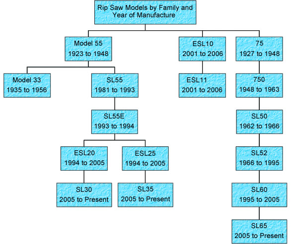
Figure No. 2 – Chronological Model of Straight Line Rip Saws Manufactured by Mereen Johnson
Beginning in 1927, the first two digits of the serial number are always the year in which the machine was manufactured. Any machines that have been remanufactured by us will have the year of remanufacture as the last two digits, preceded by the letter R. In addition, all machines built since 1963 will have a separate identification tag that was mechanically riveted to the back wall of the machine with four nail screws. If you cannot find the serial number on the machine, then someone has taken the specific effort to remove it for a particular reason. In general, machine age can be determined by the chart depicted in Figure No. 2.
Repair Parts & Serviceability
We offers immediate availability of service parts for the most commonly used items, and also maintains a large inventory of older, remanufactured items for machines as far back as 1930. In some instances, the original component is no longer available, but in virtually all of those situations a replacement component is offered to remedy the problem. Due to our continuing efforts to improve the quality of our equipment, certain original items can no longer be offered in the interest of safety. All of the remanufactured components offered by Diehl Machines are guaranteed to work, and because Diehl has all of its original manufacturing records, we guarantee the part to fit. This eliminates any concern that the user won’t get the correct part or that he’s stuck with a bill for a part that doesn’t remedy the problem. The listing below will give you an idea of some of the older remanufactured components that are available for each model of machine.
| 55 | 75 | 33 | 750 | SL50 | SL52 | SL55 | |
| Feed Drive Reducer Units | P | P | N/A | P | P | P | ON |
| Feed Control – Four-Speed Drum Switches | P | P | N/A | P | N/A | N/A | N/A |
| Spring Loaded Outfeed Tables | P | P | P | P | P | P | P |
| Stock Guides & Mounting Rails | P | P | N/A | P | P | P | ON |
| Feed Drive Motors – 4 Speed, 3HP | P | P | N/A | P | P | P | P |
| Spindle Drive Motors – 10, 15 & 20HP | P | P | P | P | P | P | P |
| Madison-Kipp brand Lubricator Units | N/A | N/A | ON | P | P | P | P |
| Gravity Type Feed Oil Reservoirs w/ Sight | P | P | P | P | N/A | N/A | N/A |
| Variable Speed Pulley – Drive Units | N/A | N/A | N/A | N/A | P | P | N/A |
| Worktable | P | P | ON | P | P | P | P |
| Pressure Bar Housings & Complete Assemblies | ON | ON | ON | P | P | P | P |
| Spindle Assemblies w/ New Spindle/Bearings | P | P | ON | P | P | P | P |
P = Available
P = Available
N/A = Not Applicable or Not Available
ON = Only New Component is Available
Glue Line Cut
While our rip saws can be used in many applications, our purpose in developing his design of the straight line rip saw was to create a superior quality cut on the edge of lumber, and eliminate the need for a lumber jointing operation. In certain applications, this quality of cut represents an edge that is not only straight, but also free from any visible detection of saw marks…and that quality of cut is what we defines as a “glue line cut”. The phrase “glue line cut” has been used for many years to determine a saw cut, high quality lumber edge surface that is prepared for the purpose of edge clamping lumber together. Describing a glue line cut is always a subjective process, that’s why we prefers to use a lumber sample to define the quality of cut that describes its definition. If you want a sample to gage the performance of your saw, or the saw you intend to purchase, contact us.
Mechanical Reliability – Items To Check
While a complete and certified evaluation of the machine and its condition relative to Diehl standards can only be confirmed by Diehl personnel, the following is a list of machine characteristics that tend to reveal its operating condition:
The ability of the saw blade to cut properly is based on the spindle and saw collar run out. If the axial run out is greater than .0015″, the saw cannot cut a glue line as previously defined. Also, spindle assembly endplay must not exceed .0010″. See Figure No. 4 for any explanation of these measurements.
Figure No. 4 – Checking for Saw Collar Run Out and Spindle Assembly End Play
Chain surface wear
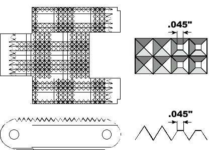
Diehl chain surfaces are completely machined with a pyramid corrugation. Once the surface on those individual pyramids reaches .025″, cutting a glue line in hardwood is not possible, and if the surfaces reach .045″, as depicted in Figure No. 5, the chain should be replaced.
Click On Any Photo For Larger View.

Figure No. 5 – Checking for Chain Corrugation Surface Wear
Chain parallelism/surface wear
Diehl chains should be interchanged every six months (based on 8 hours of daily full service) because normal wear would cause the two chains to wear in a V-pattern as viewed longitudinally. Once the chain’s V-pattern has reached .015″, a glue line is not possible, and when wear reaches .025″, as depicted in Figure No. 6, an increased probability of kickback exists, which indicates that the chains should be replaced.
Figure No. 6 – Checking for Chain Parallelism/Surface Wear
Chain Lubrication
Beginning in the late 1950’s and lasting until the pump manufacturing firm discontinued business in the early 1990’s, Diehl used a mechanical lubrication pump. Prior to this (but also including the model ESL20/25 series) the lubrication system was a gravity feed unit that wicked a felt pad, rubbing the chain on its lower return path. All of the lubrication systems work, but some have more labor involvement to insure the chain is properly lubricated. While both styles of remanufactured units are readily available from Diehl, be certain that the lubrication unit is intact and has been operative. If not, the chain may well have been damaged.

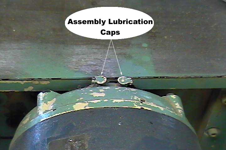
Spindle, Spindle Housing and Bearings
(1) Check the two spindle housing oil cups and determine if the unit has been regularly lubricated. If it hasn’t, a light growling noise should be present. (2) Check the air gap clearance between the rotor and stator to make certain they are not rubbing…if they are, either the spindle assembly bearings are no longer holding the spindle/rotor concentric within the stator or some mechanical damage has occurred to the rotor & stator.
Figure No. 7 – Examining the Spindle Assembly
Pressure roll assembly
Check all of the pressure rollers for wear and be certain there is no axial play in the rolls, especially the split rolls located adjacent to the blade. Then examine the roll yoke hinge pins and the bore in the pressure roll housing. If the hinge pin or bore is worn, the pressure roll housing must be dismantled, the holes bored over size and then bushed to match new pins. If the machine is a model 33, 55 or 75, the cast rolls rotate on hollow, ground, perforated shafts that wick oil for lubrication. Due to their age, these older pressure roll assemblies are generally worn to the point where extensive repair is required to make a “glue line cut”. All other models of machines use sealed ball bearings in their feed rolls.
Figure No. 8 – Checking for Axial Play in the Pressure Roll Assembly

Feed drive assembly
Up to 1960, our rip saws used a worm gear reducer, manufactured by Diehl that was integrally coupled to a four-speed motor. The worm gear in this reducer on all machines built before 1946 rotates in babbit bearings, (the worm rotates in ball bearings) so check the reducer’s output shaft and then be certain that the backlash in this gear train is not excessive. Check the gear train backlash by removing the outboard motor cover and rotate the stator or the drive chain sprocket back and forth to a total of 180 degrees. If the backlash exceeds 25 degrees of movement, the gears will probably have a short life span. Beginning with late model 75’s, ball bearings replaced the babbit, but both designs of reducers and four-speed motors are readily available from Diehl in a remanufactured condition, as are the drum switches that control the four rates of speed.
The most common wear to these components is the roller bearings on the bottom side of the stock guide. Older model 55 and 75 rip saws do not have roller bearings. If the guide rail on the machine is bent or worn with deep grooves, parallel ripping is impossible. Check the stock guide for cracks or welds, they may prevent parallel ripping as well. Many old stock guides may be cut off to make the nose end shorter which increases the minimum length stock that can be ripped.
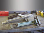
The standard stock guide supplied on every new Rip Saw with provisions for the lower anti-kickback fingers.Two different vintages of the old SL-52 stock guides are shown showing the roller bearings that should be checked.A model 75 remanufactured standard length stock guide and an old cut off guide are shown. Also a 750 guide is shown displaying the roller bearings that should be checked.